Condensers are essential heat exchange equipment in pharmaceutical and chemical manufacturing. They condense vapour (solvent vapour from reactors, distillation columns, or vacuum dryers) back to liquid for recovery, reuse, or safe disposal. Choosing the right condenser type — Shell & Tube or Box Type — affects heat exchange efficiency, footprint, maintenance requirements, and capital cost.
As a manufacturer of Shell & Tube Condensers and Box Type Condensers, Bipin Pharma Equipment supplies both types to pharmaceutical, chemical, and API manufacturing facilities.
A condenser is a heat exchanger that removes heat from a vapour stream, causing it to condense into a liquid. In pharmaceutical manufacturing, condensers are used for:
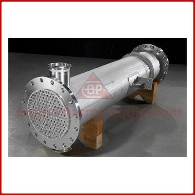
Tubular heat exchanger — vapour on shell side, cooling water in tubes (or vice versa). High efficiency, durable, suitable for high-pressure applications.
View Shell & Tube Condenser →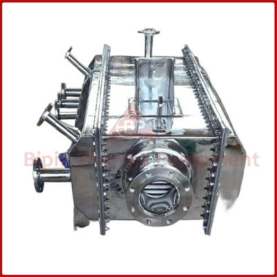
Compact flat-plate heat exchanger. Lower cost, smaller footprint, easy to clean. Suitable for low-to-medium duty solvent condensation.
View Box Type Condenser →The Shell & Tube Condenser is the most widely used condenser design in the chemical and pharmaceutical industry. It consists of a cylindrical shell containing a bundle of tubes. One fluid (typically cooling water) flows through the tubes; the vapour to be condensed flows over the outside of the tubes (on the shell side). The large surface area of the tube bundle provides efficient heat transfer.
The Box Type Condenser (also called a rectangular or plate-type condenser) has a compact box-shaped design with internal baffles and serpentine flow path. Vapour enters from the top and condensate exits from the bottom; cooling water circulates through internal coils or plates. It is simpler in construction than a shell & tube condenser and more cost-effective for smaller-scale solvent recovery applications.
| Parameter | Shell & Tube Condenser | Box Type Condenser |
|---|---|---|
| Design | Cylindrical shell + tube bundle | Rectangular box + internal baffles/coils |
| Heat Transfer Area | High (tube surface area) | Medium |
| Efficiency | High | Moderate |
| Pressure Rating | High (ASME rated) | Low–Medium |
| Footprint | Larger | Compact |
| Capital Cost | Higher | Lower |
| Maintenance | Tube cleaning required | Simple — easy access |
| Applications | Large-scale, continuous, high-pressure | Batch, pilot-scale, low-medium duty |
| Material Options | SS 316L, copper, titanium tubes | SS 316L, SS 304 |
Both condenser types serve the same fundamental purpose — vapour condensation for solvent recovery — but differ in scale, cost, and efficiency. Shell & Tube condensers are the industry standard for large-scale continuous plants; Box Type condensers are economical for batch operations and smaller facilities. Bipin Pharma Equipment manufactures both types. Contact us with your vapour load and cooling water availability for a condenser design and free quote.
Our technical team can recommend the right equipment — free consultation.
Send Enquiry Call: +91 88791 92449Manufacturer & exporter of Shell & Tube Condensers and Box Type Condensers for pharma and chemical plants. GMP-compliant, SS 316 construction. Contact us today.
Request a Free Quote View Shell & Tube Condenser